| 8.1 | Standard NAT Defined |
| 8.2 | Policy Routing NAT |
| 8.3 | NetFilter NAT |
| 8.4 | Interactions between FastNAT and NetFilter |
| 8.5 | Summary |
Dealing with the vagaries of routing structures using a dynamic routing protocol is very helpful. But it is limited in usefulness when you consider the current structure of the IPv4 Internet. Within the boundaries of a corporate network, routing is defined and scoped. Many of the routing tricks such as asymmetric, or loopy, routing, and the related structures take on a whole new meaning when applied to the border and outside of a corporate network.
While the examples you saw in Chapters 5 and Chapter 6 about border area Policy Routing work well when you consider the entire scope of the addressing space, what about cases where there is address translation? These cases of Network Address Translation, or NAT, are the topic you will explore in this chapter.
You will start by considering the definitions of NAT both from the technical and popular viewpoints. Then you will try out some of the various uses of NAT. Finally, you will explore the interactions between the firewalling functions and the Policy Routing structures.
8.1 Standard NAT Defined
The traditional definition of NAT is contained in the very term itself. Network Address Translation is the act of changing an address from one to another within the packet. While this change is usually of the source address, there is no restriction. This address changing function is essentially a router function when you consider the mechanisms. Any router, due to its very nature as an intermediary between networks, may perform the NAT function.
The early history of IPv4 networking did not need to consider this type of routing function very often. Occasionally the subject would come up, but those discussions usually were centered within fairly convoluted reasoning. The IPv4 address space does contain over 4 billion addresses and until the explosion of the Internet in the early 1990s, there was no solid reason to play with the addressing space. Thus, while NAT existed and was used it was not what is popularly referred to today as NAT.
Think of the traditional proxy server. Considering the entire sequence of events as seen from outside the server, it is essentially performing NAT. The request is made to the inside of the proxy from some client with some source address. The proxy then turns around and sends out a packet with its own source address. When the proxy receives the response, it responds back to the client.
This transaction is NAT as it fits all aspects of the definition. An address is translated by a router that spans two disparate networks. While you may not think that this scenario is a routing scenario, it certainly is. Remember that a router is defined as a system that allows traffic to be sent between networks. Traffic exists to request and receive services. So if you can sit at a machine on an IP network, make a request for a service on another network from some device, and receive that service, then you have used a router.
This is the core of considering NAT as a legitimate function within the scope of an IP network. IP addresses define service location. Receiving a service from a disparate network to your network requires a router. Whether or not that service provider actually saw your real source address is irrelevant to the networking. All that matters is that a service was transacted across network boundaries.
Seen in this light, the function of a NAT firewall is fairly obvious, especially when you consider the popular IP Masquerade. IP Masquerade is merely a many-to-one NAT. In the sense in which it is used in a Masquerading firewall, you can consider the firewall to be performing a proxy service. However, the proxy service is not specific to an application or protocol but rather to an address.
These concepts are so important because of the misconception within the networking community that NAT is somehow dirty or evil because it supposedly breaks the end-to-end model originally proposed for IP networking. The end-to-end model is the function whereby any given service transaction is performed between two, and only two, entities. But the end-to-end model is an interpretive assumption of the communication structure. For example, consider the actual communication structure of a proxy system.
The communication is initiated by a client wanting a service. The client sends a request for that service to the original service location defined by the service's IP address. This request reaches the proxy system. The proxy system intercedes into the communication. Under most protocols, the proxy system at this point would complete the initial handshake with the client on behalf of the final service. This is important because at this point the end-to-end model is satisfied from the client's point of view as the two ends, client and service, are negotiated. From the original service's point of view nothing has yet happened. So now the proxy initiates the communication with the service on behalf of the client. From the original service's point of view, the end-to-end model is complete because the client is the proxy.
Stepping back a level there are two distinct end-to-end connections that have been formed from one original request. Think of the true communication structure between two clients on either side of a router. From the layer 2 perspective, which is where the actual packet communication takes place within a local network, there are two end-to-end communications made out of one request.
Now substitute NAT for proxy. In both cases the end-to-end model is satisfied providing that the communication always includes the middle. So you must always have a bottleneck point for NAT. Or must you?
Consider the three main types of NAT: One-to-One, Many-to-One, and One-to-Many. Both Many-to-One and One-to-Many NAT are best considered as mapping types of NAT. They take a single address and spread it across many addresses. Both of these types require a single point at which to perform the mapping and through which the reverse mapping must occur. But One-to-One NAT does not require the same location to perform the mapping.
The very name One-to-One NAT implies that there is a unique correlation between two addresses. The only differentiation is direction. In one direction, address A becomes address B and in the other direction, the reverse is true. Since NAT may be considered a router function, this map function may exist in every router that crosses the boundary defining the edge over which direction changes.
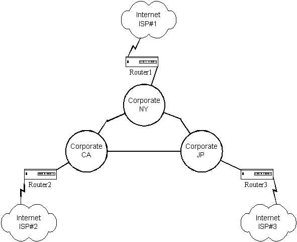
Consider the network illustrated in Figure 8.1.1. This is a fairly typical large corporate network with three primary sites. Each of the primary sites has a Policy Routing system connecting them to the Internet. Internally, all three sites are connected either through dedicated lines or VPN structures. Now imagine that there is a Web server at each location that will provide the location unique Internet services.
Each of these Web servers, call them WebA, WebB, and WebC, are addressed with internal addresses appropriate to the location. From the Internet's perspective there are three addresses assigned in DNS to each of these Web servers. The company has a registered block of IP addresses that it uses for all of its Internet-related activities. All three ISPs allow any of these addresses to enter or leave the local connection.
Since the internal addresses are in compliance with Private IP addressing (RFC-1918) the Web servers must be NATed when they route to the Internet. But which router should perform the NAT? All of them.
Think for a minute about the routing structure as it pertains to the Internet traffic. Each local machine within a corporate sector may route to the Internet by whatever path is specified as default according to the local internal router. But Internet traffic may enter the network by the closest router in relation to the traffic's origination. That is, traffic to the corporation that originates in Japan (JP) will enter the corporate network through Router3. But what if that traffic is destined for WebA?
In this scenario under traditional routing all traffic destined for WebA is given a single connection point. So consider that under traditional routing all traffic destined for WebA must be routed through RouterA whether or not RouterA is available. But under Policy Routing the traffic may enter at any of the three routers as the NAT may be performed at any of the three routers. Remember that NAT is a routing function and that this is One-to-One NAT.
In the Policy Routing scenario, all three routers will contain the NAT definitions. All three routers contain the NAT map function as each router spans the boundary defining the edge over which traffic direction changes. NAT is truly a router function and Policy Routing provides the framework for defining the entire routing function scope of application.
As you contemplate the theory of this function you need to keep in mind the definition of Address from the Policy Routing triad – Address is the location of service. Seen in this light the essential packet itself (IE: the internal data structure without addressing) is still routed and the addressing structure is merely a function of the network itself. In this sense, bearing in mind the end-to-end model, the transversal of an IPX<->IP gateway would be considered routing although most people recoil in horror when I say that. But consider the perspective that the definition of a data packet is merely the data part and not the addressing or transport. The addressing is part of the network layer and thus part of the routing structure. Remember that the triad element Route is defined as the location of Address. Thus routing is the means whereby a packet is transferred from source to destination.
8.2 Policy Routing NAT
Since NAT is a routing function, you decide you want to try out some of the various uses. You decide to return to the test setup you had in Chapter 6. This scenario is shown in Figure 8.2.1 as a refresher.
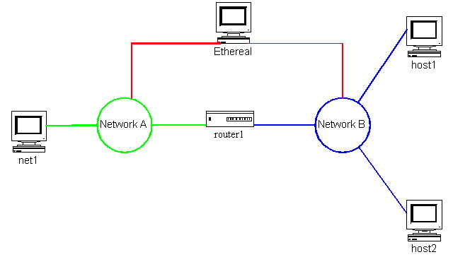
You are now going to use router1 to do some testing. To this end you setup the testing environment as follows:
| NetworkA | 192.168.1.0/24 |
| NetworkB | 10.1.1.0/24 |
| net1 | 192.168.1.1/24 |
| router1A | 192.168.1.254/24 |
| router1B | 10.1.1.254/24 |
| host1 | 10.1.1.2/24 |
| host2 | 10.1.1.3/24 |
Since you have the capability of looking at the actual packet traces, you decide to try a simple NAT in which all packets from net1 to host2 are NATed by router1 to 10.1.1.253. The ip utility allows you to perform a one-to-one NAT mapping which is called FastNAT in the kernel documentation. You decide to try out the FastNAT setup with ip. The command sequence you determine for the ip utility is as follows:
ip route add nat 10.1.1.253/32 via 192.168.1.1
ip rule add from 192.168.1.1/32 nat 10.1.1.253 prio 15000
Now from net1 when you ping, telnet, or use any other IP transport-based protocol to get to host2, you see on the packet dump that the source address has been changed to 10.1.1.253. Indeed, if you use net1 to go to any of the 10.1.1.x addresses you see that the source is changed.
This is a complete One-to-One NAT between these two addresses. If you use a packet generator or protocol that embeds the original address within the data section of the packet, you see that the only address changed is the header source. The embedded address does not change. This is the main reason certain protocols, such as IPSec, NetBEUI/BIOS and SNA/IP cannot be NATed due to their embedding the original source address within the data part of the packet. Since this is an extreme security risk on the Internet because of internal address leakage, you usually will not want to route such protocols across the Internet but rather either encapsulate them or tunnel them. In the case of IPSec and related security protocols the best solution is to always use legal IP addresses.
Curious as to the extent of the routing NAT structure you decide to see if you can perform an extended NAT mapping. You want to see if you can do a group One-to-One NAT from the address space 192.168.1.32/27 to 10.1.1.32/27 and see if the changes are mapped One-to-One. So you add the following rules:
# On net1
i=32
while [ $i -lt 64 ]; do
ip addr add 192.168.1.$i/32 dev eth0
i=$((i+=1))
done
# On router1
ip rule add from 192.168.1.32/27 nat 10.1.1.32 prio 14000
ip route add nat 10.1.1.32/27 via 192.168.1.32
From the packet traces on Network B you can see that the mapping is correctly One-to-One across the range. If you use the 192.168.1.37 source you get the translated address of 10.1.1.37. Just to make sure you change the 10.1.1.32/27 range to 10.1.1.96/27. You see that when you use the 192.168.1.37 address it gets translated to 10.1.1.101 just as a One-to-One mapping would demand.
This result allows you to have a ranged NAT defined on all of your border routers. Recalling Figure 8.1.1, you could define several sets of addresses within each of the three Corporate sites and have all three border routers contain complete range NAT maps for these subnets. As an even weirder stretch you note that with a single NIC policy router you could translate local network addresses for machines without multiple address capabilities.
If you recall the setup you had implemented in Example 6.3 from Chapter 6 where you implemented assymetric routing, you see that you can now have a distributed Policy Router setup that provides all of these services plus NAT. Consider implementing Example 6.3 on a system such as Figure 8.1.1. Assume for a moment that your company does not own its own address block but instead depends on addressing from each of the three ISPs. Your contracts with each of the three ISPs allow outbound traffic that is addressed from any of the three, but will not route inbound except to their own address blocks. This is a fairly standard multi-ISP setup in corporate environments. Are you then limited to one ISP address block for your external Web server?
No. Consider that you have control over your corporate DNS. You can specify multiple addresses for your Web server in the DNS, say one address from each ISP. Set up a single common Web server with three addresses. Each border router now has an inbound NAT mapping for the local ISP address that is DNS coded for the Web server, and three outbound NAT mappings for each of the three addresses. If you track the local routing structure on your border routers, the outbound packets from the Web server can be routed by whatever border router is closest to the destination and will receive the correct outbound address that was used to query the server. In this case you get effective failover for the Web server as seen by the outside world. If any of the ISPs is down, you still have Web services available.
Note on RFC-2267
The scenario mentioned above where one ISP allows you to route outwards through their network the set of IP addresses you obtained from a different ISP was a common practice in 1994-1996. With the advent of many of the IP Spoofing attacks and Denial-of-Service (DoS) attacks, this usage becomes a suspect activity due to the failure of traditional routing to handle spoofed addresses. RFC-2267 (January 1998) urges ISPs to implement egress filtering to prevent spoofed addresses from leaving their networks. While this mitigates some menial forms of IP Spoofing, it does little to nothing to control the notorious DDoS (Distributed DoS) attacks. DDoS attachs are launched from many remote zombie machines by a single controlling administrator. Since the zombie machines often have legitimate IP addresses from many different ISPs the inbound packets of a DDoS attack are almost impossible to distinguish from normal service requests. Indeed, the increasing implementation of RFC-2267 is driving the use of NAT as a method of maintaining a multi-ISP spanning Internet connection. Adding more extensive use of NAT to the ubiquity of DDoS slave engines paints a very frightening scenario. Hopefully, both the greater addressing space and the strict routing formalities of IPv6 will help alleviate both problems.
Of course in many of these cases there are security consequences for which you must allow. And the interactions between the security structures and the NAT structures can get very hairy. When you consider them both under the umbrella of the global routing structure, it is easier to see what points of contention will arise. Since you do run packet filtering and stateful inspection firewall systems, you turn your attention to the interactions that exist between these types of systems and your routing NAT structures.
8.3 NetFilter NAT
As you began to explore in Chapter 6>, the packet filtering structure within the Linux 2.4 series kernel is NetFilter. Because you had used the fwmark, called nfmark in NetFilter, interface to tag packets you noted that there were structures that existed to allow for NAT within the NetFilter architecture. To determine how these structures function within the Policy Routing arena, you perform a series of tests within your test network setup.
First you do some research into the style of the NetFilter structure as it pertains to the NAT function. In contrast to the bidirectional routing NAT style, NetFilter treats the direction of the NAT as an element of the NAT function. This granularity provides an additional construct that can provide for unidirectional NAT.
The two types of NAT as defined by NetFilter are the Source NAT (SNAT) and the Destination NAT (DNAT). SNAT maps outbound packets as they leave the system, hence the name Source NAT rightly implying that the source address changes. DNAT maps inbound packets as they enter the system, hence the name Destination NAT rightly implying that the destination address changes. These mappings may be applied using any of the NetFilter packet selection mechanisms, thus providing a level of granularity in the packet selection mechanisms.
After studying the NetFilter command structures, you first decide to try to rework your One-to-One NAT setup using the facilities provided by the NetFilter architecture. To this end you ensure that the iptable_nat module is loaded, see the NetFilter documentation for details, and then you set up the same One-to-One NAT using the original single address model. You end up with the following series of commands:
iptables -t nat -A POSTROUTING -o eth1 -s 192.168.1.1/32 -j SNAT --to 10.1.1.253
iptables -t nat -A PREROUTING -i eth1 -d 10.1.1.253/32 -j DNAT --to 192.168.1.1
Upon issuing any IP connection from address 192.168.1.1 to host2 you find no connection is completed. Inspecting the packet trace from Network B you see that the packets leave router1 with the NAT addressing correctly changed but that host2 does not know how to respond and ARPs repeatedly for the 10.1.1.253 address. This is unlike the situation in FastNAT where router1, the default router for host2 in both cases, received the packet and applied the translation without needing to own the address. But you find that NetFilter requires router1 to own the address 10.1.1.253. Upon adding in the command ip addr add 10.1.1.253/32 dev eth1 and running ip route flu cache, you see the NAT working correctly.
Now you know how to do a simple One-to-One mapping in NetFilter. You then try to set up the extended One-to-One NAT mapping such as you had done with the routing NAT function earlier. So you try the following set of commands:
iptables -t nat -A POSTROUTING -o eth1 -s 192.168.1.32/27 -j SNAT --to 10.1.1.64-10.1.1.95
iptables -t nat -A PREROUTING -i eth1 -d 10.1.1.64/27 -j DNAT --to 192.168.1.32-192.168.1.63
When you start testing from the 192.168.1.32 address, you notice on the packet dumps from Network B that the source addresses are incrementing upwards for every packet you send. So your first packet through from 192.168.1.32 has a source translation of 10.1.1.64, the second packet is 10.1.1.65, and so on. Definitely not what you expected and not even close to the behavior of the FastNAT. Then when you look at the verbose output of the NetFilter information, using iptables -t nat -L -n -v, you see that the DNAT setup has no packets using the rule at all. Just out of curiosity, you delete the DNAT rule and note that the operation of the system is unchanged. You finally deduce that to do One-to-One ranged NAT with NetFilter you must specify each NAT transaction independently.
For most of the cases where you would be making use of these structures you would use fairly static defined mappings anyway. The additional setup would not be a big deal unless you were doing wholesale NAT translations of complete IP address spaces, and in that case you could use the FastNAT construct.
You note that in the case where you specify this command sequence using only a single address on the one side and a range of addresses on the other that you have a clear example of One-to-Many NAT. This type of NAT structure is not very interesting for you but you can see some simple load balancing uses for it, such as multiple internal Web servers.
One of the security structures that does interest you is the use of the Many-to-One NAT. In Linux this was traditionally called IP Masquerade and you would like to implement it for some sequences of addresses. To this end you first try a quick test to masquerade all output to Network B as router1, 10.1.1.254. You implement the following commands:
iptables -t nat -A POSTROUTING -o eth1 -j SNAT --to 10.1.1.254
The packet traces from Network B show that all traffic from net1 to either host1 or host2 has a source address of 10.1.1.254. Now you know that the SNAT worked due to router1 owning the 10.1.1.254 address. This makes you wonder what constitutes ownership. From your solid understanding of the Address Triad element you suspect that any assignment of the appropriate address to the system would work. To prove your conviction you delete the preceding SNAT rule and try the following sequence:
ip addr add 172.16.13.13/32 dev dummy0
ip link set dev dummy0 up
iptables -t nat -A POSTROUTING -o eth1 -j SNAT --to 172.16.13.13
And, voila, the output from router1 into Network B has source address 172.16.13.13. Finally, to ensure that you are truly into twisted setups you add the following command:
iptables -t nat -A POSTROUTING -o eth0 -j SNAT --to 172.16.13.13
You can now see that the source address for packets on both Networks A and B is 172.16.13.13.
But there is a catch that makes you pause. You notice that the SNAT only takes place when the origination of the initial connection is from the affected network. In other words, you only see the source translation on packets that are not responses. To illustrate, you look at the sequence where you send packets from net1, 192.168.1.32 address, to host2, 10.1.1.3. The packet traces from Network B show the source translated to 172.16.13.13. But the packet traces from Network A do not show the responses from host2, 10.1.1.3, translated as you would expect from the dual SNAT. When testing from host2 to net1 you find the contrapositive sequence.
This is a function of the Connection Tracking mechanism within NetFilter. The connection tracking is what negated the DNAT in the test of One-to-One NAT and also in the testing of extended NAT. The connection tracking mechanism performs exactly as you would expect from the name. However, this is also the feature that negates the status of NetFilter NAT as a routing function and relegates it to a packet mangling function performed solely on a single system.
Consider that you have a triple connection setup as in Figure 8.1.1. You would like to implement an asymmetric, or loopy, routing structure. In this structure, traffic destined for the corporate Web server will enter only through the ISP#1 connection. When it enters it will be NATed to an address in CA. The response then returns to the Internet through ISP#2 with the same original destination address from ISP#1. Under NetFilter there are time-outs and connection tracking overhead associated with the SNAT and DNAT features. Each time a packet comes in through Router1 there is a connection track set up for the eventual "return" of the response. Similarly, each time a packet leaves through Router2 there is a connection track set up. These connection tracks take time to timeout. There is also a finite number of such connections that may be tracked due to memory and processing power on the system.
8.4 Interactions between FastNAT and NetFilter
This consideration brings you to the question of the interactions between the FastNAT and the NetFilter NAT. From your studies on the packet pathing in Chapter 3, you assume that you could have FastNAT and NetFilter too. After all, FastNAT is implemented within the RPDB while NetFilter NAT is implemented at the PRE and POST ROUTING hook points.
Such a view does not consider the reality of the kernel packet processing functions. While ideally this would be a perfect complementary function set, the reality is that there are only a few places where the packet header may be manipulated by either system. In testing the various functions you note that so long as you do not load up the actual NetFilter Conntrack module, ip_conntrack, you can do FastNAT. As soon as you load the ip_conntrack module, FastNAT stops working even without any NetFilter rules defined. So it is the Connection Tracking part of NetFilter which precludes the use of FastNAT.
At least you understand now how each of these NAT mechanisms works and some of the uses and drawbacks of each. For granularity of NAT specification and flexibility of NAT structures you can use NetFilter. For speed, Policy Routing structures, and asymmetric routing you can use FastNAT. And you do note that by a simple addition of a Policy Routing system with FastNAT on the internal network you can perform whatever pure One-to-One NAT mechanisms you wish and pass those packets unmodified through the NetFilter box.
One other thought does strike you. When you consider the FastNAT structure you realize that in the case of only needing routing-based NAT you can use the NetFilter filter and mangle tools on the same box as a FastNAT, thus providing a way to select and filter NAT-destined packets. As a quick example you consider that by defining a packet filter on the PREROUTING hook that only allows packets destined to a certain port, you effectively allow for a FastNAT based on a single port. A whole realm of possibilities opens up for those scenarios.
8.5 Summary
You have defined NAT within the Policy Routing structure. You have seen how a pure routing NAT structure runs with both asymmetric and single point setups. Using FastNAT you have explored how to translate entire address spaces from one to another bidirectionally.
You then worked through the uses of the NetFilter NAT constructs and saw how these constructs complement the FastNAT structure. You understand how each type of NAT has a use within the overall network structure. Also, you determined that the two structures do not at this time coexist with each other.
But as you think about these uses of NAT you begin to ponder why it will be important in the long term. In IPv4 NAT has grown from an esoteric oddity to a daily necessity. But you know that IPv6 does not need or allow NAT. You decide to find out what Policy Routing is all about under Ipv6.