| 3.1 | The Triad Elements - Address, Route, Rule |
| 3.2 | RPDB - The Linux Policy Routing Implementation |
| 3.3 | System Packet Paths - IPChains/NetFilter etal. |
| 3.4 | Summary |
The case for implementing Policy Routing and the related structures is easy to see. What is harder to grasp is the scope and the impact on the packet-passing paths within a TCP/IP network. The question of where and how the packets are passed from and through a network-connected device can deeply affect the points of application of Policy Routing structures.
This chapter will explore the structure that allows packets to pass through a system. Most of this discussion will center on understanding the logic of the packet traversal. At times you may need to delve into the actual operation of the system innards.
The overall structure of this chapter is written with an eye to generalize as much as possible to ease understanding across disparate systems. The implementation structure will be drawn from the posits and foundations of the need for Policy Routing as espoused to a large extent in Chapter 2. Where possible the examples of usage for Policy Routing as arisen from the limitations of traditional routing will be referenced to clarify why particular Policy Routing structures exist.
3.1 The Triad Elements - Address, Route, Rule
The core of Policy Routing rests on the use of three elements. These are the traditional elements of Address and Route as extended by Policy Routing, and the additional Policy Routing element: Rule.
| Address | defines the location of a service. |
| Route | defines the location of the address. |
| Rule | defines the location of the route. |
These three elements comprise the structure around which the implementation of Policy Routing is built. All three play unique roles that can act singularly, but they are most effective when combined. The interactions between these elements provides the flexibility, and the complexity, seen in Policy Routing.
The order in which you look at these elements determines the output you derive from the system. Because each element is totally independent of the others, you can consider the effects of each on the system. The interactions then add the extra dimension to complete the scope. In Chapter 5, "Simple Network Examples," and Chapter 6, "Complex Network Examples," you will actually implement some real examples using these elements individually and then in concert. To understand the implementation details you need to understand first the background of each element.
3.1.1 Address
The first element of the triad is Address. This element refers to the location of a service or of a set of services. The Address specifies the object that is acting or is acted upon. This sounds very general, but you must step back and consider how any service is provided on a network.
For example, consider how you access a Web server on the current IPv4 Internet. The first step is usually to try to connect to the system. You type the protocol and address into your browser, such as http://www.policyrouting.org. Then your browser asks your DNS server to resolve the name. Resolving the name means that the browser is asking for the IP address associated with that name; that is, you are requesting the http service from that IP address.
Now that IP address may not have anything to do with any physical machine. In Chapter 5 you will actually run through examples of this type of behavior. But for the moment consider what use you are making of this address. To your browser it serves as a marker that defines where the browser should go to look for the information it is seeking. It defines to your browser the location of that service. In order to understand and for a more complete definition of IP address as location function refer to RFC 2101 and also read through the definition of Weak ES model in RFC-1122 Section 3.3.4.2 - Multihoming Requirements.
Up to this point you have looked at the destination address. This is one of two core parts of the traditional routing. As you saw in Chapter 1, traditional routing is destination based. And in traditional routing, the destination implicitly and explicitly referred to is the destination IP address within the packet header.
To see the depth of this statement, suppose that you have decided to implement a new packet header for your new "SuperTrad" traditional IPv4 router. This header will be added as a wrapper when the packet traverses a "SuperTrad"-only network. Don't laugh unless you too remember systems such as ProNet, the fight between NetBUEI and NetBIOS, or have tried to import an EIGRP-only network into a gated environment.. In your new header you decide that all you need is the destination IP address and checksum of the whole packet. After all, nothing else matters to the routing. This packet would function fine in almost all of the routing cases in IPv4 for the last twenty years.
Now you come to Policy Routing. In Policy Routing, as it should have been in traditional routing, both of the addresses within the IPv4 packet header are important. Indeed, the entire packet header can be used to define a route. This elevates the source IP address to the same intense scrutiny as the destination. If you think about it, if the source address had been as important in traditional routing as the destination address you would not see any spoofed addresses. After all, when a router is paying attention to the source address and it is looking for a specific set of source addresses, using a faked source address (spoofing) is limited to the finite set of allowed internal source addresses. That legal set could be shrunk to one address, which makes spoofing impossible.
Both of the addresses provided in an IPv4 and IPv6 packet are important in Policy Routing. And the importance is not limited to the actual single address itself. There is a whole method for specifying groups of addresses similar to the way you specify networks. The notation used is the same - CIDR (Classless InterDomain Routing) style masking.
The result of applying a CIDR scope to an address is used to associate the address with the network as it needs to be defined for the purpose of implementing the Policy Routing structure. It should not be confused with the definition of the network by a CIDR mask. In Chapter 5 there is a set of examples you can work through to see exactly how this works.
In brief, consider that the address CIDR mask has nothing to do with the network CIDR mask. If I had a network that is 192.168.1.0/24 and I decide to use the address 192.168.1.1/25, I can. I can even use the address 192.168.1.1/16. The network does not and should not care what my address scope is so long as I obey the routing rules of the network and provide the machine with the correct local network broadcast address which may differ from the address scope. For the moment, you should just remember that the scope of an address does not necessarily have anything to do with the definition of the network.
The scope of both addresses within the packet header is either explicitly stated when dealing with the address or it defaults to the network scope. In both cases, once the scope is given it associates the address with some grouping, which then defines the relevant route used. This brings you to the second core element of the Policy Routing triad, routes.
3.1.2 Route
Essentially, routes are little changed from the traditional variety. They code the forward method for getting to the destination address. And when you consider the larger viewpoint this makes sense. Most of the routing that is done is straightforward. You have a destination in mind and you want to get there by the best means possible.
All of the discussion in Chapter 2 merely adds to this point. When you look into Policy Routing, what you notice is that it helps you make a decision on where to route a packet based on alternate criteria. The method of actually selecting a route is changed, but the method of using the route once obtained is the same.
What is different when contrasting the Policy Routing route element with the traditional method is more versatility and flexibility in specification and destination options. The traditional route command allows you to specify a gateway and some options on the path to that gateway for a network or host destination address. Additionally, most route command implementations allow you to specify a "reject" or "denied" route option. This is essentially the same as a route lookup failure and returns an ICMP Type 3 Code 0 "network unreachable" error.
Besides the standard gateway object, in the Policy Routing schema a route may provide reference to an outgoing source address, interface, or specify an error destination. The errors returned may exist in the ICMP codes or the packet may be simply dropped or changed. When the packet is changed, the action becomes a NAT (Network Address Translation) function, which you will see in Chapter 8, "NAT Functions." The additional destinations are not required but are specified on an implementation basis. Within Linux you will see that the Policy Routing subcommand has a range of additional targets for the route object. Some of these targets refer to types of network structure such as broadcast or multicast. Others provide alternate destination targets for control such as prohibit or blackhole. You will use these features in Chapter 5 and Chapter 6 when you start to see how to implement Policy Routing structures.
For now you want to consider the route element of the Policy Routing triad as an advanced version of the traditional route structure. Indeed, for simple networks where you are providing standard routing functions the Policy Routing implementation reduces to the traditional specification. But the greater functionality is always there for use.
3.1.3 Rule
So if the route element is not all that different, how do you select a route using all of the advanced methods discussed in Chapter 2? Where are the route by source address, route by packet header data, and the other selection mechanisms?
This is where the rule element comes into play. Think of the rule as a method for implementing ACLs (Access Control Lists) for routes. The rule allows you to specify the filters that match packets, and which route structure to select when the filter does match. Because the filter is part of the rule selection mechanism, you can also use rules to specify other advanced options such as destination targets and NAT functions.
Using a rule you can perform the most common Policy Routing function, route by source address. The rule can specify to select a packet based on whether or not the source address of the packet falls into a designated address scope. If it does match, the rule states which route structure to use or other destination to choose. But if you stop to think about this for a moment, you realize that on a system where you only have one routing table a rule set is usable only under limited conditions.
3.1.3.1 Multiple Routing Tables
In a single routing table system, such as current network router devices, or most operating systems, all of the routes specified are in a single group called a table. This table is then read through (in network speak the route is "looked up") sequentially and the longest match of the packet destination is made. This longest match then returns the gateway to which to forward the packet.
Suppose you have three routers to the same network. Each router has a different speed connection to your network core. Which one should you use in your routing table? Even under OSPF this type of routing structure still results in a single "best" route for the condition of use.
Consider this conundrum in a different light. Most of your network clients only need limited access to a particular network. They would be fine on a slow link. A select group of your network clients needs a higher rate access to this network. If you have only one routing table, you can only put in one route to this destination network. Which one do you use? In this case even if you use rules to select the traffic, where are you going to end up sending them? To the routing table.
Thus the implementation of the rule in Policy Routing implies that for true global structure you must also implement multiple routing tables. A complete Policy Routing structure is found in the Linux kernel, version 2.1 and higher. It provides full use of Address, Multiple Independent Route Tables, and a Rule selection mechanism that can interact bidirectionally with the route tables.
3.2 RPDB - The Linux Policy Routing Implementation
Under Linux, the implementation of Policy Routing structure is carried out through the mechanism of the Routing Policy DataBase (RPDB). The RPDB is the cohesive set of routes, route tables, and rules. Since addressing is a direct function of these elements, it also is part of the system. What the RPDB primarily does is provide the internal structure and mechanism for implementing the rule element of Policy Routing. It also provides the multiple routing tables available under Linux.
Linux's RPDB and the complete rewrite of the IP addressing and routing structures in kernel 2.1 and higher sustains 255 routing tables and 2^32 rules. That is one rule per IP address under IPv4. In other words, you can specify a rule to govern every single address available in the entire IPv4 address space. That works out to over 4 billion rules.
The RPDB itself operates upon the rule and route elements of the triad. In the operation of RPDB, the first element considered is the operation of the rule. The rule, as you saw, may be considered as the filter or selection agent for applying Policy Routing.
The following text about the RPDB and the definition of Policy Routing is adapted from Alexey Kuznetsov's documentation for the IPROUTE2 utility suite, with Alexey's permission. I have rewritten parts of the text to clarify some points. Any errors or omissions should be directed to me.
Classic routing algorithms used on the Internet make routing decisions based only on the destination address of packets and, in theory but not in practice, on the TOS field. In some circumstances you may want to route packets differently, depending not only on the destination addresses but also on other packet fields such as source address, IP protocol, transport protocol ports, or even packet payload. This task is called Policy Routing.
To solve this task, the conventional destination-based routing table, ordered according to the longest match rule, is replaced with the RPDB, which selects the appropriate route through execution of rules. These rules may have many keys of different natures, and therefore they have no natural order except that which is imposed by the network administrator. In Linux the RPDB is a linear list of rules ordered by a numeric priority value. The RPDB explicitly allows matching packet source address, packet destination address, TOS, incoming interface (which is packet meta data, rather than a packet field), and using fwmark values for matching IP protocols and transport ports. Fwmark is the packet filtering tag that you will use in Chapter 6 and is explained later on in this Chapter in the section "System Packet Paths -IPChains/NetFilter."
Each routing policy rule consists of a selector and an action predicate. The RPDB is scanned in the order of increasing priority, with the selector of each rule applied to the source address, destination address, incoming interface, TOS, and fwmark. If the selector matches the packet, the action is performed. The action predicate may return success, in which case the rule output provides either a route or a failure indication, and RPDB lookup is then terminated. Otherwise, the RPDB program continues on to the next rule.
What is the action semantically? The natural action is to select the nexthop and the output device. This is the way a packet path route is selected by Cisco IOS; let us call it "match & set." In Linux the approach is more flexible because the action includes lookups in destination-based routing tables and selecting a route from these tables according to the classic longest match algorithm. The "match & set" approach then becomes the simplest case of Linux route selection, realized when the second level routing table contains a single default route. Remember that Linux supports multiple routing tables managed with the ip route command.
At startup, the kernel configures a default RPDB consisting of three rules:
| Priority 0: Selector = match anything | Action = lookup routing local table (ID 255) |
| The local table is the special routing table containing high priority control routes for local and broadcast addresses. Rule 0 is special; it cannot be deleted or overridden. |
| Priority 32766: Selector = match anything | Action = lookup routing main table (ID 254) |
| The main table is the normal routing table containing all non-policy routes. This rule may be deleted or overridden with other rules. |
| Priority 32767: Selector = match anything | Action = lookup routing table default (ID 253) |
| The table default is empty and reserved for post-processing if previous default rules did not select the packet. This rule also may be deleted. |
Do not mix routing tables and rules. Rules point to routing tables, several rules may refer to one routing table, and some routing tables may have no rules pointing to them. If you delete all the rules referring to a table, then the table is not used but still exists. A routing table will disappear only after all the routes contained within it are deleted. Remember that a route is the location of the address while the rule is the location of the route.
Each RPDB entry has additional attributes attached. Each rule has a pointer to some routing table. NAT and masquerading rules have the attribute to select a new IP address to translate/masquerade. Additionally, rules have some of the optional attributes that routes have, such as realms. These values do not override those contained in routing tables; they are used only if the route did not select any of those attributes.
The RPDB may contain rules of the following types:
| unicast | The rule prescribes returning the route found in the routing table referenced by the rule. |
| blackhole | The rule prescribes dropping a packet silently. |
| unreachable | The rule prescribes generating the error Network is unreachable. |
| prohibit | The rule prescribes generating the error Communication is administratively prohibited. |
| nat | The rule prescribes translating the source address of the IP packet to some other value. |
You will see how these rule actions operate primarily in Chapter 5 and Chapter 6. There you will make hands-on use of the command set and implement several Policy Routing structures.
The RPDB was the first implementation of and first mention within the Linux community of the concept of Policy Routing. When you consider that the ip utility was first released in late spring of 1997, and that Alexey's documentation was released in April of 1999 coinciding with the official Linux 2.2 kernel release in May of 1999, then you realize that the Linux Policy Routing structure is already over five years old. In Internet time that is considered almost ancient. But as with most new network subjects, such as IPv6 and Policy Routing, Linux leads the way.
The RPDB itself was an integral part of the rewrite of the networking stack in Linux kernel 2.2. The Policy Routing extensions are accessed through a defined set of additional control structures within the Linux kernel. These extensions are the NETLINK and RT_NETLINK objects and related constructs. If you are curious about the programmatic details you can look through the source to the ip utility itself. The call structure and reference to the kernel internals is laid out quite well.
One of the important features that makes the RPDB implementation so special is that it is completely backward-compatible with the standard network utilities. You do not need to use the ip utility to perform standard networking tasks on your system. You can use ifconfig and route and get along quite fine. In fact, you can even compile the kernel without the NETLINK family objects and still use standard networking tools. It is only when you need to use the full features of the RPDB that you need to use the appropriate utility.
This backward compatibility is due to the RPDB being a complete replacement of the Linux networking structure, especially as it relates to routing. The addressing modalities for Policy Routing, as discussed in the "Address" section earlier in this chapter (and illustrated in depth in Chapter 5), were also implemented as part of this change. But the main changes, besides the addition of the rule element, were the changes to the route element. Drawing upon Alexey's documentation again I provide the following information on the route element construct.
In the RPDB, each route entry has a key consisting of the protocol prefix, which is the pairing of the network address and network mask length, and optionally the TOS value. An IP packet matches the route if the highest bits of the packet's destination address are equal to the route prefix, at least up to the prefix length, and if the TOS of the route is zero or equal to the TOS of the packet.
If several routes match the packet, the following pruning rules are used to select the best one:
1. The longest matching prefix is selected; all shorter ones are dropped.
2. If the TOS of some route with the longest prefix is equal to the TOS of the packet, routes with different TOS are dropped.
3. If no exact TOS match is found and routes with TOS=0 exist, the rest of the routes are pruned. Otherwise the route lookup fails.
4. If several routes remain after steps 1-3 have been tried, then routes with the best preference value are selected.
5. If several routes still exist, then the first of them is selected.
Note the ambiguity of action 5. Unfortunately, Linux historically allowed such a bizarre situation. The sense of the word "the first" depends on the literal order in which the routes were added to the routing table, and it is practically impossible to maintain a bundle of such routes in any such order.
For simplicity we will limit ourselves to the case wherein such a situation is impossible, and routes are uniquely identified by the triplet of prefix, TOS, and preference. Using the ip command for route creation and manipulation makes it impossible to create non-unique routes.
One useful exception to this rule is the default route on non-forwarding hosts. It is "officially" allowed to have several fallback routes in cases when several routers are present on directly connected networks. In this case, Linux performs "dead gateway detection" as controlled by Neighbor Unreachability Detection (nud) and references from the transport protocols to select the working router. Thus the ordering of the routes is not essential. However, in this specific case it is not recommended that you manually fiddle with default routes but instead use the Router Discovery protocol. Actually, Linux IPv6 does not even allow user-level applications access to default routes.
Of course, the preceding route selection steps are not performed in exactly this sequence. The routing table in the kernel is kept in a data structure that allows the final result to be achieved with minimal cost. Without depending on any particular routing algorithm implemented in the kernel, we can summarize the sequence as this: Route is identified by the triplet {prefix,tos,preference} key, which uniquely locates the route in the routing table.
Each route key refers to a routing information record. The routing information record contains the data required to deliver IP packets, such as output device and next hop router, and additional optional attributes, such as path MTU (Maximum Transmission Unit) or the preferred source address for communicating to that destination.
It is important that the set of required and optional attributes depends on the route type. The most important route type is a unicast route, which describes real paths to other hosts. As a general rule, common routing tables contain only unicast routes. However, other route types with different semantics do exist. The full list of types understood by the Linux kernel is as follows:
| unicast | The route entry describes real paths to the destinations covered by the route prefix. |
| unreachable | These destinations are unreachable; packets are discarded and the ICMP message host unreachable (ICMP Type 3 Code 1) is generated. The local senders get error EHOSTUNREACH. |
| blackhole | These destinations are unreachable; packets are silently discarded. The local senders get error EINVAL. |
| prohibit | These destinations are unreachable; packets are discarded and the ICMP message communication administratively prohibited (ICMP Type 3 Code 13) is generated. The local senders get error EACCES. |
| local | The destinations are assigned to this host, the packets are looped back and delivered locally. |
| broadcast | The destinations are broadcast addresses, the packets are sent as link broadcasts. |
| throw | Special control route used together with policy rules. If a throw route is selected, then lookup in this particular table is terminated, pretending that no route was found. Without any Policy Routing, it is equivalent to the absence of the route in the routing table, the packets are dropped, and ICMP message net unreachable (ICMP Type 3 Code 0) is generated. The local senders get error ENETUNREACH. |
| nat | Special NAT route. Destinations covered by the prefix are considered as dummy (or external) addresses, which require translation to real (or internal) ones before forwarding. The addresses to translate to are selected with the attribute via. |
| anycast | not implemented The destinations are anycast addresses assigned to this host. They are mainly equivalent to local addresses, with the difference that such addresses are invalid to be used as the source address of any packet. |
| multicast | Special type, used for multicast routing. It is not present in normal routing tables. |
Linux can place routes within multiple routing tables identified by a number in the range from 1 to 255 or by a name taken from the file /etc/iproute2/rt_tables. By default all normal routes are inserted to the table main (ID 254), and the kernel uses only this table when calculating routes.
Actually, another routing table always exists that is invisible but even more important. It is the local table (ID 255). This table consists of routes for local and broadcast addresses. The kernel maintains this table automatically, and administrators should not ever modify it and do not even need to look at it in normal operation.
In Policy Routing, the routing table identifier becomes effectively one more parameter added to the key triplet {prefix,tos,preference}. Thus, under Policy Routing the route is obtained by {tableid,key triplet}, identifying the route uniquely. So you can have several identical routes in different tables that will not conflict, as was mentioned earlier in the description of action 5 and "the first" mechanism associated with action 5.
These changes to the route element provide one of the core strengths of the RPDB, multiple independent route tables. As you will see in Chapter 5, the rule element alone can only perform a selection or filter operation. It is still up to the route to indicate where the packet needs to go next. Adding on top of these elements the QoS mechanisms to determine and set the TOS field and the ability to route by the TOS field provides you with the most powerful and flexible routing structure available under IPv4 and IPv6.
In summary, the RPDB is the core facility for implementing Policy Routing under Linux. The RPDB streamlines the mechanism of dealing with rules and multiple route tables. All operations of the rule and route structure are centralized into a single point of access and control. The addition of various alternate actions and destinations for routes and rules through the RPDB allows you to fine tune the mechanism of Policy Routing without needing to hack sections of the networking code.
3.2.1 CISCO Policy Commands
Note that there are policy actions that are contained within Cisco IOS 11.2 and above. If you are curious about this check out the Cisco documentation on the Web (http://www.cisco.com/warp/public/732/jump.shtml).
Cisco uses multiple types of matching criteria (incoming interface, source or destination address, mac address or ip precedence) to make a choice as to what policy to enact upon a particular packet. Route maps are used to set as many policy actions as you like based on the match conditions. Route maps are enacted line by line, with a match criteria and a set criteria. You can even use committed access rate (CAR) to rate limit various types of traffic based on these same match criteria. The routing table is not even consulted unless there is no match for a particular packet. If there is not a match and set, then the route table is used as a default condition. There is an example of how to use the Cisco route-map command at the end of Chapter 5.
3.3 System Packet Paths - IPChains/NetFilter
Understanding the RPDB brings up the question of at what point within the system the RPDB operates. To understand this within the context of the system you need to first see the logic of packet traversal within the system. The best way to approach this traversal is to consider how the packet filtering mechanisms treat this flow.
The various packet filtering mechanisms within the Linux kernel structures deal directly with the conceptualization of the packet flow as a means to identify the control points. They do this so that they may apply their security mechanisms at the control points. These control points are also of interest to the Policy Routing structure because these are the same control points that you would think to operate upon with Policy Routing structures.
3.3.1 IPChains - Kernel 2.1/2.2
Start by considering the logical structure of the packet filtering mechanism within the Linux 2.1/2.2 kernel series. This kernel series is also the one within which the RPDB was implemented and the full scope of Policy Routing structures was developed. The relevant mechanism is that of IPChains. As the name implies, the IPChains packet filtering mechanism considers the implementation of logical control through "chains" of commands implemented to operate upon the defined control points.
The conceptual model is taken from the older IPFWADM model that was implemented in the Linux 1.3/2.0 series kernels. The model describes the traversal of a packet within the system by differentiating between two distinct types of packet sourcing. The first type of packet is one that originates externally to the system and then traverses the system. The second type of packet is one that is either originated from within the system or is originated externally but ends within the system.
This differentiation of origination actually suits the consideration of Policy Routing structures very well. There is a difference when a packet is sourced from the internal system as opposed to a transverse packet passing through the system. Suppose, for example, that you want to apply TOS tagging to the packet. The point at which you apply the tagging would be different for an internally generated packet than for one that passes through the system. In both cases, however, you will probably generate the tagging at an interface.
The concept as proposed with the release of IPFWADM and extended by IPChains is that there are three primary locations in the packet path: the INPUT, OUTPUT, and FORWARD chains. These are the locations at which you would want to intercept the packet. A transverse packet that crosses through the system crosses all three chains, whereas a packet that originates from within the system only crosses two.
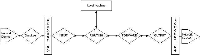
Considering again the transverse packet, the logic of traversal is as shown in Figure 3.3.1.
You can see the three main chains, INPUT, OUTPUT, and FORWARD. Think again of the differentiation of the packet paths. Any packet can take one of three paths through the system:
1. A packet externally sourced that is destined for a service on this machine will enter the system, pass through INPUT, and be routed to the Local Machine.
2. A packet internally sourced that is destined for an external destination will be routed to OUTPUT.
3. A transverse packet will pass through INPUT, FORWARD, and OUTPUT, in that order.
Now a note on the actual logic of the packet paths. In all of these considerations the most important one is the location of the ROUTING diamond. This is the location of the RPDB. A packet filter may act on packets entering the system through the INPUT chain. And it may act on packets exiting the system through the OUTPUT chain. But the FORWARD chain actions are modified by the result of the output from the ROUTING. You will go through the examples of how to change the NAT and IP MASQUERADE addresses using this logic in Chapter 8. For now, you should note that the actions of the ROUTING control the connectivity to the Local Machine and also the connectivity to the FORWARD chain.
So using the IPChains packet filter you can modify and preselect the packets that are seen by the RPDB. Thus this acts as an extension of the RPDB rules. One of the more powerful features is the allowance in the RPDB rules to act upon a "fwmark." A fwmark is a binary code set in the packet header by the packet filter software. Using this fwmark you can implement packet filter routing mechanisms. An even more powerful feature is the use of the u32 classifier for setting the TOS field in the packet. You will use both of these functions in Chapter 6 to perform advanced selection.
All of these types of tagging functions take place at the INPUT or OUTPUT chains. Now the interactions with the RPDB are only within the ROUTING section, but the interactions with Policy Routing are throughout the system. Consider the example of applying TOS tagging to the packet. If the packet is locally sourced, you would apply the TOS tag after the OUTPUT chain because that is where the tc utility operates. Conversely, for traversal packets you can apply the TOS tag either before the INPUT or after the OUTPUT chain. Also the IP MASQUERADE function of IPChains is applied within the FORWARD chain while the related NAT functions of the RPDB are applied within the ROUTING diamond. These concepts will become points of contention in Chapter 8.
3.3.2 NetFilter - Kernel 2.3/2.4
This contention of packet path location brings up the latest iteration of packet filtering in Linux. NetFilter is the extension of the traditional IPChains to cover state tracking functions. The new concept is to consider pure packet selection mechanisms as defining packet filtering in contrast to defining any packet selection mechanisms that change the packet information as packet mangling. This makes sense from many standpoints. It even casts a good light on the traditional split of consideration between routing and TOS/QoS structures as you will see in Chapter 6.
What NetFilter does is make this division of function obvious. Consider the packet paths in Figure 3.3.2.
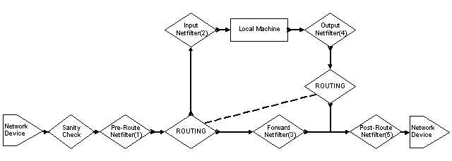
Note that the dotted line tying together the two routing diamonds indicates that these are the same function, the RPDB. The reason for the split is that the routing function is entered in different places in the packet path.
This is due to another change in the packet path policy within NetFilter. The Input(2) and Output(4) chains now only refer to the Local Machine. When you consider that the primary function of a firewall is to protect machines behind it, and that implies transverse packets, then the packet path for NetFilter is much cleaner. Additionally, by placing the INPUT and OUTPUT chains as operating only upon the Local Machine you can create secured server machines.
Consider the path for a transverse packet. It enters the system and is processed by the entrance packet mangling and tagging stage, Pre-Route(1). This stage is where you would apply packet mangling operations such as fwmark and TOS/QoS tagging. The packet then enters the RPDB to obtain routing. From the RPDB it enters the primary firewall chain, Forward(3). The Forward chain is where the firewalling decisions are made. After the Forward chain it enters the exit packet mangling and tagging stage, Post-Route(5). The Pre-Route and Post-Route locations are where you would also apply NAT and IP MASQUERADING functions. Note that these NAT functions are not the same as the RPDB NAT. Indeed you will see the differences between RPDB NAT and NetFilter NAT in Chapter 8.
This transverse packet path, assuming you do not do any packet mangling, only then needs to be inspected by two entities, the RPDB and the Forward firewall chain. This is a great improvement in speed and logic when you start considering the interactions of Policy Routing and firewalling. For the purposes of a secured service machine, things are also more logically handled.
Consider the path for an externally sourced packet destined for an internal service. It enters the system and is processed by the entrance packet mangling and tagging stage, Pre-Route(1). This stage is where you would apply packet mangling operations such as fwmark and TOS/QoS tagging or perhaps the NetFilter NAT. The packet then enters the RPDB to obtain routing and is routed to the Input(2) chain. The Input chain provides the firewalling functions for packets destined to the Local Machine services.
The reverse scenario is the packet path for an internal service sourced packet destined for an external system, such as the reply packet to the one described in the previous paragraph. It exits the Local Machine and enters the Output(4) chains, which provides the firewalling functions. It then enters the RPDB for route processing and exits the system via the exit packet mangling and tagging stage, Post-Route(5).
Note that in all of these packet paths, ignoring the Mangle functions of the Pre/Post ROUTING chains, the packet never crosses through more than one packet filter chain and in all cases the packet gets processed by the RPDB. So all of the functions associated with the Policy Routing structures under the RPDB may be applied to the packet.
3.4 Summary
You have seen the fundamental triad of Policy Routing and how these elements are implemented within the Linux kernel through the RPDB. You then traced through the logic of the packet paths for the packet filters and the RPDB action locations. Now you understand the logic of the traffic flow for Policy Routing in Linux.
Chapter 4 will cover the usage and operation of the ip utility from Alexey Kuznetsov. This is the main utility implementing all of Policy Routing with the exception of TOS/QoS. Within the utility suite, however, is the tc utility, which performs all of the TOS/QoS functions of Policy Routing. After you have learned about the ip utility you will start to delve into hands-on experiences with Policy Routing by implementing a series of increasingly complex examples.
As you go through the examples and usages of the utilities try to see how the Triad operates in those situations. Remember:
| Address | defines the location of a service. |
| Route | defines the location of the address. |
| Rule | defines the location of the route. |